Guitar switch replacement dillemna, help needed. - 06/14/19 08:54 PM
OK I can take a saxophone apart (hundreds of pieces) and put it together, but this is my first adventure with a broken guitar.
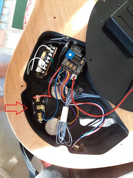
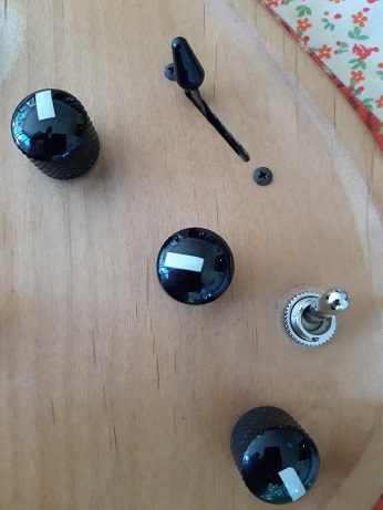
I have a Parker Maxxfly USA made guitar. The pickup switch is a blade but the switch that selects either the magnetic pickups, piezo pickup or both is a toggle.The mag/piezo toggle fell apart.
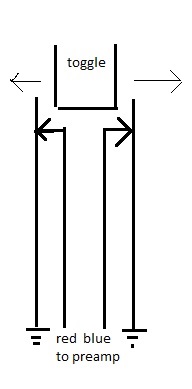
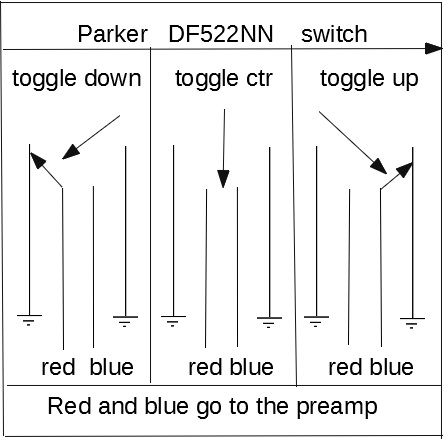
From what I can see it looks like two switches with a nylon probe between them attached to the toggle. In the center position both switches seem to be closed with two metal blades touching each other. When the switch is moved to either extreme, it separates the blades on the opposite side, leaving only one side closed.
There are four solder lands on the edge of the switch. The two outside are ground and the two inside go to the pickups, one to the piezo and the other to the mags.
Is this a DPDT on/on/on switch? If not, please correct me.
(I've been googling but since my local guitar store doesn't have a replacement and I have to have it sent to me, I want to make sure I get it right the first time).
The nut that holds it to the guitar, thus I assume the hole is 7/16" - at least by holding it up to a ruler.
What would you recommend for the sturdiest, most reliable replacement?
Thanks:
The guitar, the switch farthest from the neck is the one in question.
Couldn't get the pictures to post (I don't know why) so here are the links'
http://www.nortonmusic.com/pix/NN08_right.jpg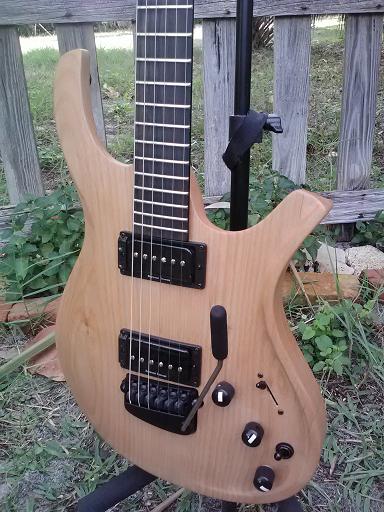
Switch pictures to follow:
http://www.nortonmusic.com/pix/Parker_Switch_001.jpg
http://www.nortonmusic.com/pix/Parker_Switch_002.jpg
http://www.nortonmusic.com/pix/Parker_Switch_003.jpg
http://www.nortonmusic.com/pix/Parker_Switch_004.jpg
Thanks!
Notes
I have a Parker Maxxfly USA made guitar. The pickup switch is a blade but the switch that selects either the magnetic pickups, piezo pickup or both is a toggle.The mag/piezo toggle fell apart.
From what I can see it looks like two switches with a nylon probe between them attached to the toggle. In the center position both switches seem to be closed with two metal blades touching each other. When the switch is moved to either extreme, it separates the blades on the opposite side, leaving only one side closed.
There are four solder lands on the edge of the switch. The two outside are ground and the two inside go to the pickups, one to the piezo and the other to the mags.
Is this a DPDT on/on/on switch? If not, please correct me.
(I've been googling but since my local guitar store doesn't have a replacement and I have to have it sent to me, I want to make sure I get it right the first time).
The nut that holds it to the guitar, thus I assume the hole is 7/16" - at least by holding it up to a ruler.
What would you recommend for the sturdiest, most reliable replacement?
Thanks:
The guitar, the switch farthest from the neck is the one in question.
Couldn't get the pictures to post (I don't know why) so here are the links'
http://www.nortonmusic.com/pix/NN08_right.jpg
Switch pictures to follow:
http://www.nortonmusic.com/pix/Parker_Switch_001.jpg
http://www.nortonmusic.com/pix/Parker_Switch_002.jpg
http://www.nortonmusic.com/pix/Parker_Switch_003.jpg
http://www.nortonmusic.com/pix/Parker_Switch_004.jpg
Thanks!
Notes